Commodore 64 Power Supply Repair
2012-06-03 15:13
The repair I'm describing here involves mains voltage, which can be very dangerous if not handled properly.
Do not even think about trying this yourself if you are not absolutely sure what you are doing!
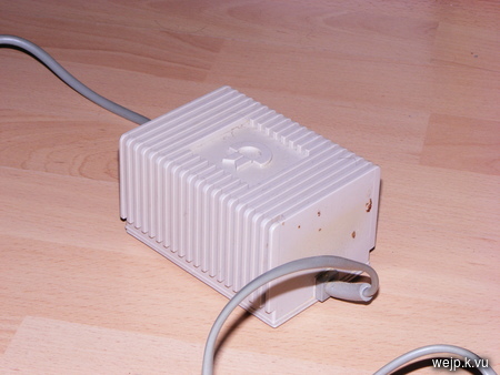
The original power supply of my C64 was broken. Unfortunately it was one of those power supplies where everything inside the case has been glued into one big block filling the entire case. Repairing such a mess seemed next to impossible.
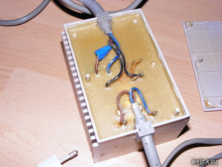
Knowing that the power supply had one of those inefficient linear voltage regulators, I did not actually consider removing the glue from the circuit and actually repairing the old power supply. I still wanted to have a power supply that looks like the original one, though.
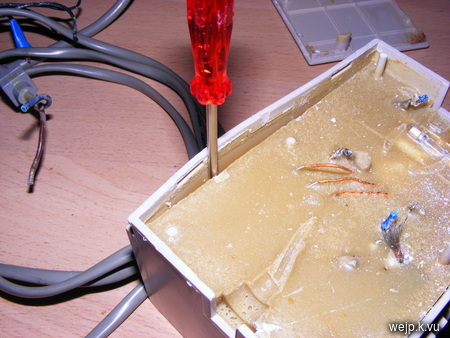
So I decided to remove the block of glue from the case.
Using a screwdriver to loosen the glue from the case and then (gently) smacking the case onto the floor allowed me to remove the broken circuit
without destroying the case.
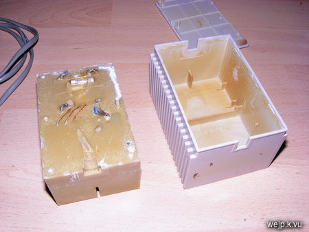
Now I had an empty case, ready to be filled with a new power supply.
As I wanted to avoid working with mains voltage as much as possible, I decided to use a transformer, just like in the old power supply, but instead of using a linear regulator to get the 5 volts required by the C64, I chose to use a switching voltage regulator (LM2576). Another reason for using a transformer
were the 9 V AC the C64 requires for its real time clock and for some external extensions.
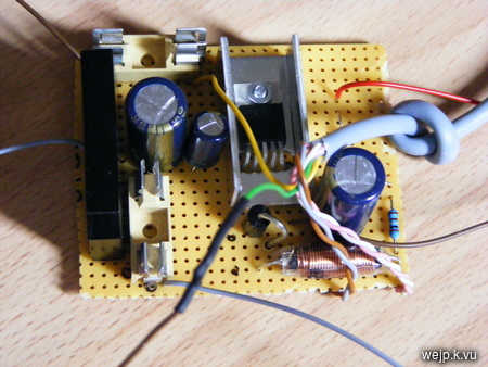
My circuitry is rather simple, consisting of a 36 VA transformer with two 9 V AC outputs with 2 A each. I have protected each output of the
transformer with a slow 2 A fuse. One of the two 9 V outputs is directly wired to the output connector, the other one is going through a recitifier and a 2200 µF capacitor. At that point I have about 13 V DC which the switching regulator reduces to 5 V, without producing much heat.
The switching regulator circuit is based on the example circuit that can be found in the
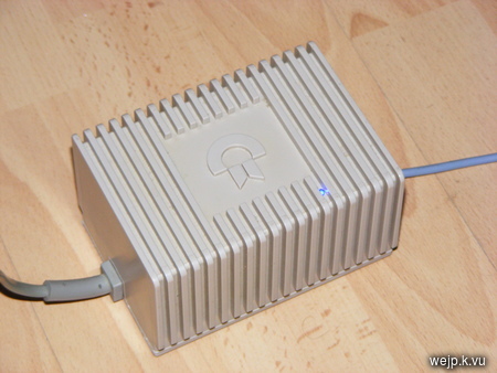
regulator's datasheet. At the output of the regulator I have connected a LED so one can see if it is powered on. The 5 volt output is then routed to the output connector just like the 9 volt output.
I have drilled a small hole into the case for the new LED.
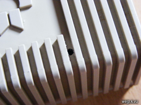
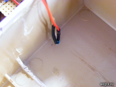
The new circuit with the transformer fits nicely in the old case.
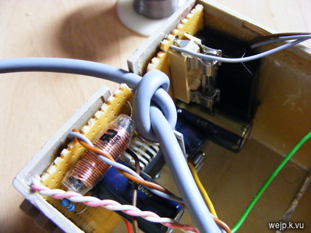
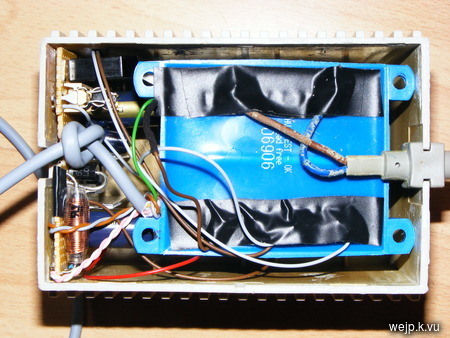
The total power consumption of the C64 with my new power supply is a little over 8 watts. The power supply does not get noticably warm, unlike the old power supply.
The repaired power supply looks almost exactly like the original one.
 Update 2016-04-06: Schematic
I have been asked for a schematic a couple of times. So here it is.

The correct value for the transformer's primary rating depends on your mains voltage, of course.
2012-06-04 13:27:05
looks nice :P
i can't believe they did that to the original transformer, what's the purpouse of the resin? not like there was super secret technology inside....xD
and wikipedia says that was the main cause of failure because the epoxy resin caused them to overheat.
2012-07-26 12:35:12
Hello. Do you have a schematic and partnumbers? How much did it cost totally?
/ddm
2012-07-26 13:13:54
Hi ddm,
the most expensive part is the transformer, everything else costs less than 10 €/USD. The transformer is a generic 36 VA transformer with 2 x 9 V / 2 A one the secondary side. A little less current than those 2 A would be fine as well, in case you have an old transformer lying around. Other than that, I have built the regulator circuitry according to the datasheet ( https://www.national.com/ds/LM/LM2576.pdf ). The only thing that's not in the datasheet's schematic is the rectifier and the large 2200 µF capacitor I have put after the rectifier.
I have been using the -ADJ version of the LM2576 which allows you to choose the output voltage through resistors. I've used that one, just because I had those regulators lying around. If you need to buy the regulator anyway, I'd suggest using the LM2576-5.0 version.
2012-07-26 19:04:56
Hello. Do you think this could be an alternative to your 36VA ?http://se.farnell.com/myrra/45062/transformer-30va-115-230v-2x-9v/dp/1777965
2012-07-26 22:00:32
ddm, yes, that one should work fine.
2014-04-10 21:18:57
Hi mate!
Nice work i had the same idea as you! And ive drawn a schematic using the circut provided in the pdf for the lm2567.
One thing i wonder why did you keep the smaller 100uf capacitator at the input when addding the 2200uf one?
Cant you just remove that?
/Dan
2014-04-11 20:56:37
Danne: You probably can get away with just using one large filter capacitor on the input, if placed really close to the regulator's input pin. I've used the combination of one large cap and the 100 µF cap, because the datasheet suggests to do that.
It also suggests to keep the connection of the input cap to the regulator input as short as possible, which is a little easier with a smaller cap (I know that my placement of the cap isn't exactly ideal in that regard ;).
You really don't want any weird oscillation there and following the datasheet's suggestions can't hurt.
The thing with electrolytic capacitors is, it is not only the capacitance that counts, but also their internal resistance. Having two caps in parallel certainly lowers the total resistance, which is always a good thing when used with switching mode regulators.
Btw, the two capacitors actually each have a different purpose: The large is used as a filter cap (to create a DC voltage out of the AC-like voltage coming from the recitifier), while the smaller one is used as a bypass cap for the regulator (to help deliver current fast when needed by the regulator).
2016-02-08 23:07:07
Nice work! It inspired me to build my own replacement PSU! My original is still working and the outputs are in a good range (5.16VDC and ca. 10.34VAC).
But the new one.. As a prototype, the DC line seems to be OK, I guess, the wires on the PCB are too thin, but it works. Output DC is 5.10V unloaded, and 4.96V loaded. I can turn the C64 on.
But the 9VAC is really bad It is between 11.40V and 12.50V or sometimes more unloaded, and when I plug the home made PSU in, the fuse in the C64 blows immediately. C64 was turned off, so the SID is still alive. There is also a "thunder" on the old C64 monitor, much bigger then with the original PSU.
I use a JESIVA 2x9VAC 35VA transformer. What type do you use? What could I check? What could be wrong? Good questions, heh? Thanks for any idea!
2016-02-17 13:23:40
Mate: There is nothing unusual about the rather high unloaded voltage of the AC line. This is to be expected and is most likely not the reason for the blown fuse. Your 35VA 2x9V AC transformer should work fine for the purpose when wired correctly. It is hard to tell what exactly is wrong, but I suggest that you check for unwanted connections between the two outputs. The AC output should be completely separated from the DC output when not connected to the C64. There should be not measurable connection when measuring the resistance between any of the output pins between AC and DC outputs, so a multi meter should always show infinite resistance. Only measure resistance when the power supply is turned off. Also make sure that the output voltages are actually on the correct pins of the connector (you probably have already verified this).
2016-03-11 18:54:46
Hello,
Im interested to you C64 power suply replacement. May I have the schematic, please ?
Thanks,
Dave
2016-03-16 09:29:51
Hi dave,
I'll probably draw a schematic for the power supply in a few days and add it to the blog post.
2016-05-01 19:24:03
Very useful post for clues on how to build a new PSU. Looking around I reckon that a "Mini LM2956 module" from ebay for a small number of pound/dollars would be an even easier, smaller and more convenient solution to the circuitry.
2016-05-05 08:42:58
Andy: Sure, you can use pretty much any switching mode regulator as long as it has an output voltage of 5 V and it can deliver at least 2 A. Of course you don't have to build the circuit yourself if there is a suitable module available.
2016-12-28 15:23:53
Could I get your help in selecting a good transformer from either Jameco or DigitKey? Don't want to get the wrong one. Thanks.
2016-12-30 10:58:26
Carlos: There is not all that much that can go wrong if you choose the correct input and output voltages and power (VA). The required input voltage obviously depends on the country you are living in. It must be rated for your mains voltage. The transformer must have two outputs with 9 V each and it should have about 36 VA. You can pick a transformer with more VA, but it will be more expensive and also bigger so you probably don't want to do that. Usually you can pick between different types of transformers (toroidal, pcb mount, etc.). They will all work fine, but they need to be mounted differently, so it depends on the case you are using. For the original C64 power supply case, I recommend a tranformer like the one I've used.
2019-03-03 22:40:15
After searching the web for DIY C64 psu I found 99.9% of phone-charger crap coupled to another off-the-shelf-brick chain horrors; yours is A TRUE DIY PROPER PSU replacement for the C64 and u get a huge plus for fitting the improved switching version into the same old plastic original case.I'm downloading your schematic and building my own to resurrect an old C64 I received from a friend.Thank you very much, great job!
2020-04-16 02:46:34
Hi, do you know if the origional one had the rifa capacitor that is known to go bad?
2020-04-17 11:23:37
Than Oliver: Hard to tell, since the whole thing was potted, but given its age, that's certainly possible. What I do suspect though as the usual failure mode is normal electrolytic caps losing their capacity. Also the rectifier diodes seem to be too small to properly handle the current and as such are driven beyond their specification making them prone to fail. If I remember correctly at least in the non-potted versions they used 1N4001 or similar for currents well above 1 A.


