
I've got one of these simple remote controlled RGB LED strips. Using the IR remote control that came with it to select colors is fine, but I wanted to be able to control it through a computer. That way it would be possible to do things like turning it off when playing a movie for instance, or using it to signal any kind of event.
")
There are different options on how to achieve that. I could have replaced the whole LED controller circuitry with my own, but I didn't want to do that. What I decided to do instead is create a small circuit that emits IR signals that the original controller understands. That way I can still use the original remote control and do not have to modify any of the original LED strip components. The downside to this is that I am stuck with the capabilities of the original controller, which are rather limited.
There are different options on how to achieve that. I could have replaced the whole LED controller circuitry with my own, but I didn't want to do that. What I decided to do instead is create a small circuit that emits IR signals that the original controller understands. That way I can still use the original remote control and do not have to modify any of the original LED strip components. The downside to this is that I am stuck with the capabilities of the original controller, which are rather limited.
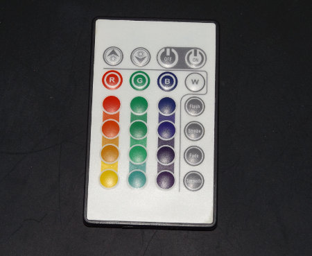
My LED strip came with a remote control that looks like this:
Since I had no idea what protocol the remote control uses, I first had to figure that out. To do that I hooked up a TSOP31238 IR receiver to my oscilloscope.

Pretty much all common IR remote controls work with carrier frequencies in the range of 36 to 40 kHz. For testing purposes I chose the TSOP31238 receiver with 38 kHz that I conveniently had lying around. Those receiver components are rather tolerant when it comes to the exact carrier frequency, so that it should work even if the frequency is not exactly 38 kHz.
The receiver component has to be connected to a 5 V power supply. It then outputs a demodulated signal of what the remote control sends.
There seem to be four major protocols when it comes to consumer IR remote controls. The Philips RC5 and RC6 protocols, the NEC protocol and the Sony protocol. The latter seems to be used only by Sony devices, while the others are used by a wide variety of devices.
With the output hooked up to my oscilloscope, when pressing a button on the remote control I get a signal like this (I have added the red annotations to the screenshot):

The TSOP31238 IR receiver outputs an active low signal, so the bursts received from the remote control are shown as low signals. Also, the TSOP31238 demodulates the signal, which in this case simply means that it removes the carrier frequency from the signal. IR protocols usually use an on/off modulation, meaning there are only two possible states during transmission: Either the carrier frequency is transmitted or it is not.
The signal from the remote control starts with a long burst (9 ms) followed by a pause half as long. I've marked this with a red 1 in the screenshot. This is typical for the NEC protocol. So at this point I have assumed that this is probably the protocol that is being used, and as it turns out, it almost is.
With the NEC protocol, a "0" is transmitted with a burst (with 562.5 µs when using a 38 kHz carrier) followed by a pause with the exact same length. A "1" is transmitted with the same burst followed by a longer pause (1.6875 ms when using a 38 kHz carrier).
What follows is the 8 bit device address (which is 0 for this device, so all 8 bits are "0") (2) followed by the logical inverse of that byte (all 8 bits "1") (3). But wait, something is wrong here. When looking at the waveform, in the supposedly inverted device address byte there is one bit that isn't inverted after all. As it turns out, there is an extended version of the protocol, where the redundancy of the device address is sacrificed for a vastly increased amount of possible address values (16 bits for a total of 65536 - 256 values of the original protocol where the second byte is an exact inversion of the first = 65280). As it remains to be seen, it is unclear why they used this variant.
After that the command byte (4) followed by its logical inverse (5) is transferred (only partly visible in the screenshot). Of each byte the least significant bit is transmitted first. The transmission ends with a final 562.5 µs burst.
The buttons on the remote control simply use the numbers 0 to 23 starting with 0 for the top most left button.
With all that figured out, it was time to design a simple circuit. I chose to use an ATiny2313A. For communication with the computer this time I simply use the controller's UART which I have hooked up though a USB-to-serial cable to a PC. The circuit is very simple with only a few components. I drive the IR LED through a transistor which is connected to an output pin of the micro controller. The datasheet of the IR LED (Vishay TSUS5402) specifies the maximum current allowed for continuous operation (150 mA) and bursts (300 mA). I have limited the current through the IR LED such that I never exceed the maximum allowed current even for continuous operation. That means that even in case of a software error causing the IR LED to be turned on permanently, no damage would occur.
If I had configured the circuit to drive the IR LED with a higher current for improved range, it probably would be useful to add some protection circuitry, that would prevent damage to the IR LED in case of a software error. This could be achieved by powering the transistor through a capacitor instead of directly through the supply voltage. The capacitor itself would then slowly be charged through a resistor. That would still allow for high currents for short bursts, but would prevent continuous high current flow through the IR LED.
Since I use the UART to talk to the micro controller, the controller's crystal has to be selected carefully to be able to use a valid UART speed. Details about this can be found in the datasheet. When using 9600 bps UART speed, a 4 MHz crystal works okay with a rather low error. For higher speeds such as 115200 bps the error would be to high, so a better matching frequency should be selected. I have written the software in a way that both a 4 MHz crystal for operation at 9600 bps can be used as well as a 14.7456 MHz crystal for a UART speed of 115200 bps with perfect timing.

The final schematic is fairly simple and consists of only a few components. Depending on the controlling host's I/O voltages, the supply voltage should be selected appropriately. Both 3.3 V and 5 V work fine, but the component values in the schematic are selected for 3.3 V. For 5 V operation the value of the IR LED current limiting resistor R2 should be increased to 39 ohm. That way the IR LED runs at about the same current of approximately 100 mA as in the 3.3 V configuration.
At 3.3 V supply voltage, the idle power consumption of the circuit is about 0.6 mA when running at 4 MHz and about 1.8 mA when running at 14,7456 MHz. Without putting the CPU into power saving mode, the power consumption rises to about 5.1 mA (from 1.8 mA). To be able to wake up from sleep mode, I have connected the PD2/INT0 I/O pin to the RXD pin, so every time something is sent over the serial interface an interrupt will be triggered which can be used to wake up from sleep.

While implementing the micro controller firmware, it turned out that the IR receiver of the LED strip was rather primitive. For one it completely ignored the device identifier transmitted. I could use any value and the receiver would still accept the signal. This makes me wonder why they even bothered to use the extended NEC protocol. Ignoring the device identifier is a bad idea, because it means the receiver also interprets signals transmitted by other remote controls using the same protocol.
To make things even worse, the receiver also ignored the value of the inverted command byte. That byte is sent so the transmission is more robust against errors. A proper receiver would not accept a command when the command byte and the inversion of that byte don't match. But not this one. As long as the command byte itself is within range it happily executes the command. This explains why it would sometimes select a wrong color when using the normal remote control.
Although the remote control appears to emit a signal that looks like the extended NEC protocol, I chose to implement the standard NEC protocol, since the receiver ignores the address bytes anyway. This seems to be more useful if used for other projects. Of course it can be changed fairly easily as well.
The source code for my controller firmware is available for download. I've done all my development on Linux and I have used the AVR GCC to compile the project. A Makefile is included, which can be used to build the project and program it onto the micro controller using avrdude.
serial_ir_remote-0.2.tar.gz (10 kB, GPLv2)
md5sum: 2315c984df93c6dceb9eba3135be71ea
I generate the carrier frequency of about 38 KHz with the ATtiny's PWM generator. The actual data is then modulated onto the signal by turning the PWM signal on and off at the right times.
To transmit a command via infrared a simple text based command has to be send to the ATiny2313A over the serial interface. For example
Since there is nothing specific to that LED strip in my circuit and firmware, it can be used to control pretty much any device using the NEC IR protocol. The carrier frequencies differ slightly between devices, so that might need adjustment, but often that's not even necessary since many receivers are fairly tolerant to slight variations in carrier frequency.
To test the serial communication with the circuit, on a Linux machine the screen utility can be used, like so:
Since I had no idea what protocol the remote control uses, I first had to figure that out. To do that I hooked up a TSOP31238 IR receiver to my oscilloscope.
Pretty much all common IR remote controls work with carrier frequencies in the range of 36 to 40 kHz. For testing purposes I chose the TSOP31238 receiver with 38 kHz that I conveniently had lying around. Those receiver components are rather tolerant when it comes to the exact carrier frequency, so that it should work even if the frequency is not exactly 38 kHz.
The receiver component has to be connected to a 5 V power supply. It then outputs a demodulated signal of what the remote control sends.
There seem to be four major protocols when it comes to consumer IR remote controls. The Philips RC5 and RC6 protocols, the NEC protocol and the Sony protocol. The latter seems to be used only by Sony devices, while the others are used by a wide variety of devices.
With the output hooked up to my oscilloscope, when pressing a button on the remote control I get a signal like this (I have added the red annotations to the screenshot):
The TSOP31238 IR receiver outputs an active low signal, so the bursts received from the remote control are shown as low signals. Also, the TSOP31238 demodulates the signal, which in this case simply means that it removes the carrier frequency from the signal. IR protocols usually use an on/off modulation, meaning there are only two possible states during transmission: Either the carrier frequency is transmitted or it is not.
The signal from the remote control starts with a long burst (9 ms) followed by a pause half as long. I've marked this with a red 1 in the screenshot. This is typical for the NEC protocol. So at this point I have assumed that this is probably the protocol that is being used, and as it turns out, it almost is.
With the NEC protocol, a "0" is transmitted with a burst (with 562.5 µs when using a 38 kHz carrier) followed by a pause with the exact same length. A "1" is transmitted with the same burst followed by a longer pause (1.6875 ms when using a 38 kHz carrier).
What follows is the 8 bit device address (which is 0 for this device, so all 8 bits are "0") (2) followed by the logical inverse of that byte (all 8 bits "1") (3). But wait, something is wrong here. When looking at the waveform, in the supposedly inverted device address byte there is one bit that isn't inverted after all. As it turns out, there is an extended version of the protocol, where the redundancy of the device address is sacrificed for a vastly increased amount of possible address values (16 bits for a total of 65536 - 256 values of the original protocol where the second byte is an exact inversion of the first = 65280). As it remains to be seen, it is unclear why they used this variant.
After that the command byte (4) followed by its logical inverse (5) is transferred (only partly visible in the screenshot). Of each byte the least significant bit is transmitted first. The transmission ends with a final 562.5 µs burst.
The buttons on the remote control simply use the numbers 0 to 23 starting with 0 for the top most left button.
With all that figured out, it was time to design a simple circuit. I chose to use an ATiny2313A. For communication with the computer this time I simply use the controller's UART which I have hooked up though a USB-to-serial cable to a PC. The circuit is very simple with only a few components. I drive the IR LED through a transistor which is connected to an output pin of the micro controller. The datasheet of the IR LED (Vishay TSUS5402) specifies the maximum current allowed for continuous operation (150 mA) and bursts (300 mA). I have limited the current through the IR LED such that I never exceed the maximum allowed current even for continuous operation. That means that even in case of a software error causing the IR LED to be turned on permanently, no damage would occur.
If I had configured the circuit to drive the IR LED with a higher current for improved range, it probably would be useful to add some protection circuitry, that would prevent damage to the IR LED in case of a software error. This could be achieved by powering the transistor through a capacitor instead of directly through the supply voltage. The capacitor itself would then slowly be charged through a resistor. That would still allow for high currents for short bursts, but would prevent continuous high current flow through the IR LED.
Since I use the UART to talk to the micro controller, the controller's crystal has to be selected carefully to be able to use a valid UART speed. Details about this can be found in the datasheet. When using 9600 bps UART speed, a 4 MHz crystal works okay with a rather low error. For higher speeds such as 115200 bps the error would be to high, so a better matching frequency should be selected. I have written the software in a way that both a 4 MHz crystal for operation at 9600 bps can be used as well as a 14.7456 MHz crystal for a UART speed of 115200 bps with perfect timing.
The final schematic is fairly simple and consists of only a few components. Depending on the controlling host's I/O voltages, the supply voltage should be selected appropriately. Both 3.3 V and 5 V work fine, but the component values in the schematic are selected for 3.3 V. For 5 V operation the value of the IR LED current limiting resistor R2 should be increased to 39 ohm. That way the IR LED runs at about the same current of approximately 100 mA as in the 3.3 V configuration.
At 3.3 V supply voltage, the idle power consumption of the circuit is about 0.6 mA when running at 4 MHz and about 1.8 mA when running at 14,7456 MHz. Without putting the CPU into power saving mode, the power consumption rises to about 5.1 mA (from 1.8 mA). To be able to wake up from sleep mode, I have connected the PD2/INT0 I/O pin to the RXD pin, so every time something is sent over the serial interface an interrupt will be triggered which can be used to wake up from sleep.
While implementing the micro controller firmware, it turned out that the IR receiver of the LED strip was rather primitive. For one it completely ignored the device identifier transmitted. I could use any value and the receiver would still accept the signal. This makes me wonder why they even bothered to use the extended NEC protocol. Ignoring the device identifier is a bad idea, because it means the receiver also interprets signals transmitted by other remote controls using the same protocol.
To make things even worse, the receiver also ignored the value of the inverted command byte. That byte is sent so the transmission is more robust against errors. A proper receiver would not accept a command when the command byte and the inversion of that byte don't match. But not this one. As long as the command byte itself is within range it happily executes the command. This explains why it would sometimes select a wrong color when using the normal remote control.
Although the remote control appears to emit a signal that looks like the extended NEC protocol, I chose to implement the standard NEC protocol, since the receiver ignores the address bytes anyway. This seems to be more useful if used for other projects. Of course it can be changed fairly easily as well.
The source code for my controller firmware is available for download. I've done all my development on Linux and I have used the AVR GCC to compile the project. A Makefile is included, which can be used to build the project and program it onto the micro controller using avrdude.
serial_ir_remote-0.2.tar.gz (10 kB, GPLv2)
md5sum: 2315c984df93c6dceb9eba3135be71ea
I generate the carrier frequency of about 38 KHz with the ATtiny's PWM generator. The actual data is then modulated onto the signal by turning the PWM signal on and off at the right times.
To transmit a command via infrared a simple text based command has to be send to the ATiny2313A over the serial interface. For example
S 0 3followed by a line break would send the device ID of 0 and the command ID of 3. As mentioned earlier, the device ID is ignored by the receiver for my particular LED strip, so any value will do. The controller will reply with "OK" when a command it understands has been submitted. In all other cases it will reply with "ERROR".
Since there is nothing specific to that LED strip in my circuit and firmware, it can be used to control pretty much any device using the NEC IR protocol. The carrier frequencies differ slightly between devices, so that might need adjustment, but often that's not even necessary since many receivers are fairly tolerant to slight variations in carrier frequency.
To test the serial communication with the circuit, on a Linux machine the screen utility can be used, like so:
screen /dev/ttyUSB0 115200That would make screen open a connection on the first USB attached serial port at 115200 bps. After successfully connecting to the device, commands can be typed in the terminal and will be sent to the controller. After pressing return, the controller will evaluate the command and send it over IR and print "OK" over the serial connection or if it is invalid it will just print "ERROR".