While the CH341A Mini Programmer is a very versatile device - not only can it be used as an SPI flash programmer, but also as a UART and possibly even an AVR programmer, it is known to have a design flaw, probably due to a misinterpretation of the fairly vague CH341A datasheet by the people who have designed the Mini Programmer.
The Problem
The programmer supplies the CH341A chip with 5 V, which causes all of the data lines to also have 5 V logic levels. At the same time, the voltage supplied to the SPI flash memory is 3.3 V. This does not make any sense and causes pretty much all SPI flash memory chips to be operated outside of their specifications - either because they are not 5 V parts in the first place or because the chip's data pin voltage levels are above the supply voltage which is almost always forbidden (due to excess current flowing through the chip's protection diodes).The reason for this is probably that the CH341A datasheet mentions that the chip can be powered from either 5 or 3.3 V and the fact that the CH341A has an internal 3.3 V voltage regulator. That regulator is only used for the CH341's internal micro controler core, but not the chip's I/O, which results in the situation described above.
The Fix
Fortunately, the Mini Programmer does have a separate 3.3 V regulator on the PCB. This only powers the socket for the SPI flash, but with a small modification can be used to also power the CH341A.The common fix for this, as suggested by Ian.M on the EEVBlog forums, is to lift the power pin of the CH341A and running a wire from the 3.3 V regulator to the lifted pin as well as to pin 9.
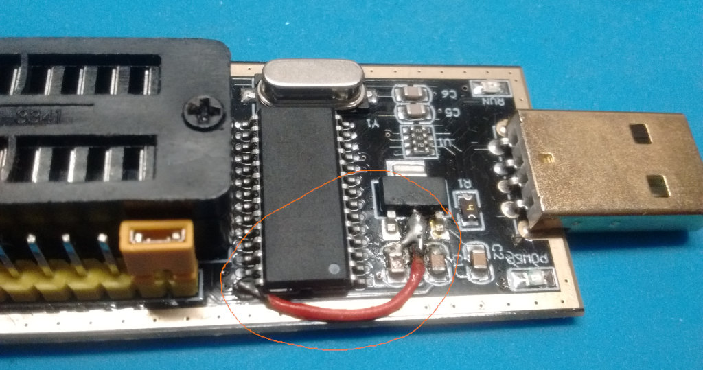
Since there is a fairly high risk of me ripping out the pin while lifting it, I didn't want to lift the pin. Instead I cut a power trace on the bottom of the PCB and then simply soldered a wire between the power pin 28 and the output of the 3.3 V regulator as well as C4 which is directly connected to pin 9 of the CH341.
Fortunately, user jakeisprobably in the same thread has reverse-engineered the Mini Programmer PCB and posted very useful pictures and the Mini Programmer schematic, which made it easy to identify the PCB trace that needed to be cut.
Here is a picture of the top side with the installed bodge wire.

Here is the bottom of the programmer with the cut PCB trace highlighted.

The only difference between this fix and the pin lifting fix is that the 5 V pins of the pin headers around the SPI chip socket do no longer carry 5 V but instead just 3.3 V. Not an issue for me. Actually, it probably even reduces the risk of me messing things up by accidentally connecting some 3.3 V component to 5 V.
Overall it was a pretty easy fix and the programmer works fine now and operates the attached 3.3 V flash memory chips within their specifications.
