
Introduction
This is an IKEA SPÖKA light. It is a small night light resembling a little ghost.
Originally powered by an internal rechargable battery, the light is controlled by a single button. When pressing that button it starts cycling through various color combintations. When you press that button again it freezes the current color. That's all it can do. Depending on the model the colors can be a combination of either blue and green or red, orange and blue.
Inspired by another SPÖKA mod I decided to also modify such a light, but instead of wirelessly communicating with the device, I wanted to be able to control it through USB. As the power requirements of the SPÖKA light are very low, it can easily be powered through the USB as well.
I chose the blue/green model of the SPÖKA light. First I disassembled
the light, which by the way is not that easily done, because the silicone skin is attached very tightly.

This is how the inner body looks like.

Here is another picture showing the inner parts of the light. The light comes with an internal 3.6 V/550 mAh battery constisting of three AAA NiMH batteries.

The internals of the SPÖKA light I am using differs considerably from the one being used in the hack mentioned above (the more round one). The main differences are that the round SPÖKA seems to use single-color LEDs, although in three different colors, instead of only two colors. Also, the round SPÖKA's main circuit is placed on a single PCB, while the one I am using consists of two PCBs for the main circuit.
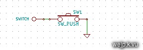
So my SPÖKA light comes with three PCBs: One very tiny one located in the head of the ghost, containing nothing but the button.
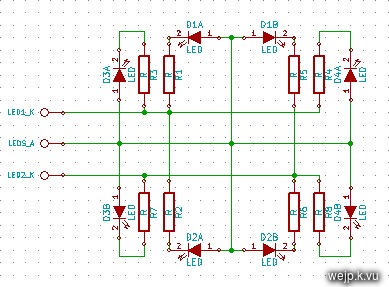
The second PCB contains four two-color-LEDs (blue/green) and current limiting resistors.

The LEDs for each color are connected in parallel. The Anodes of all LEDs are connected together. I have drawn a schematic showing the wiring of that PCB.
Then there is a third PCB containing an unknown IC, probably some sort of micro controller and a few other components (like resistors and transistors for switching the LEDs and some simple charging circuitry for the battery). I did not bother analyzing that circuit in detail, as the IC on the PCB is completely blank with no marking whatsoever.

I decided to replace that PCB and keep the other two (with the button and the LEDs). As a micro controller I chose an ATtiny25 AVR controller (with 2048 bytes of flash memory and 128 bytes of SRAM). To be able to talk to a computer over USB I chose the great V-USB firmware-only USB implementation.
As I intended to use the light with a computer all the time, I had no need for the internal battery either, so I removed that as well.

The new controller board connected to the LEDs and the button can be seen in the following picture.

Because of the Mini USB connector's different shape and position, I had to enlarge the hole for the connector. I did not modify the silicone skin in any way, though.


The new PCB needs to be of exactly the same size as the old one to fit into its place. You can see the (partly) reassembled SPÖKA light in the following pictures.


The reassembled inner body...

...and the USB cable attached to the night light still without its skin...

..and then with the skin reattached:


The new firmware can operate in a few different modes. The default mode allows the light to be turned on even without a computer. With the button one can cycle through three colors (blue, green, turquoise). An algorithm for fading through various color combinations did not fit into the 2K of controller memory, so that mode is not available in stand-alone mode. It is available when connected to a computer, though.
When connected to a computer, one can configure the light in different ways. Each color can be turned on individually (with configurable brightness). Also, the button's behavior can be configured. By default, the button works as described above (cycling through those three colors). Another possible configuration for the button is to only turn the light off when it had been turned on previously. The third option for the button is to do nothing to the lights but instead report a button press through USB to the computer. That way the software on the host side can decide how to react to a button press.
When connecting the device to a Linux computer, the kernel log says something like the following about the device:
The Makefile for the firmware can build the firmware (make hex) and flash it onto the controller (make program). To build it the avr-gcc is needed, to flash it avrdude is needed. Also, as the call to avrdude for flashing is specific to the programmer used, the AVRDUDE=.. line in the Makefile needs to match the programmer that is being used.
The software consists of two components. A little daemon that does the actual talking with the SPÖKA light and a command line utility that talks to the daemon. That way, one can tell the daemon to e.g. slowly cycle through different colors and then the daemon does its job in the background until one tells it to do something else. With that software it would also be possible to configure the light such that it flashes when an email or instant message arrives, given that the IM/email program supports calling external programs for such an event.
To be able to talk to the USB device, the user running the daemon needs the permissions to do that. When running it as root, it automatically has all the permissions it needs, so there is nothing to be done in that case. When running it with an ordinary user, the neccessary permissions can be granted through an udev rule. Such rules can be created by adding a file to the /etc/udev/rules.d/ directory. So to allow user access to the SPÖKA USB device, I have added a file called "10-spoka.rules" with the following content:
When the host software has been compiled with the Makefile inside the "tool" directory, there is an executable file called "spokausb". Executing that file with the -d option starts the daemon in the background:
To terminate the daemon one can simply kill it.
First, the circuit could be modified to support a third color, so the round SPÖKA light could be used as well. This would require to disable the RESET pin on the ATtiny25 to be able to use it as an ordinary I/O pin. Once that has been done, the controller can no longer be reprogrammed using the normal programming mode. So either one needs to program it before setting the fuses, or a programmer supporting high voltage serial programming is needed.
Another possible modification would be to use hardware PWM to control the LEDs, instead of doing that with a software routine. The advantage of this would be that the PWM could be done without the CPU. That would leave the CPU with basically only handling the USB stuff. This would also mean, that USB transfers would not be able to interrupt the PWM routine. Because the hardware PWM can only be used on specific pins one would have to re-route one of the LEDs, which is kind of difficult to do on that small PCB. Also, as there are only two PWM channels available on the ATtiny25 this would not be possible for the three color SPÖKA light.
As already mentioned abobe, another thing that comes to my mind is the addition of a capacitor with about 100 µF in parallel to the power supply line, to stabilize it a bit. When using a very long USB wire (several meters) this might actually be necessary. Due to the very limited amount of available space, I did not include such a capacitor. I had no problems with unstable supply voltage, though.
Of course one could also use a larger micro controller (as in higher memory capacity) like an ATtiny45 or ATtiny85 (which come with twice/four times the the memory) and add more features to the firmware. I simply liked the idea of using one of the smallest AVR controllers. It is also the cheapest of those three.
Last but not least, one could modify the firmware such that it acts like a real HID device and exposes the button of the SPÖKA light as a one key keyboard. This would certainly require a controller with more memory (e.g. ATtiny45).
There are probably a lot more things one could do differently/better. If you have any ideas, suggestions or questions, you are welcome to leave a comment or write me an e-mail.
spokausb-0.1.0.tar.gz (Firmware and host utility (96 kB, GPLv2)
md5sum: bf50712e1b5160dfd82f7ee50e9909aa
The video should play fine in at least the Chrome, Firefox and Opera browsers.
Disassembling the light
Here is a picture showing how I removed the skin. Rather than trying to pull the skin off the SPÖKA's body (well, I actually tried, but it did not work ;), I pushed the lower half of the skin to the inside like you can see on the picture. Afterwards I was able to remove the skin rather easily. I did not use any tools here, to avoid damaging the skin.This is how the inner body looks like.
Here is another picture showing the inner parts of the light. The light comes with an internal 3.6 V/550 mAh battery constisting of three AAA NiMH batteries.
The internals of the SPÖKA light I am using differs considerably from the one being used in the hack mentioned above (the more round one). The main differences are that the round SPÖKA seems to use single-color LEDs, although in three different colors, instead of only two colors. Also, the round SPÖKA's main circuit is placed on a single PCB, while the one I am using consists of two PCBs for the main circuit.
So my SPÖKA light comes with three PCBs: One very tiny one located in the head of the ghost, containing nothing but the button.
The second PCB contains four two-color-LEDs (blue/green) and current limiting resistors.
The LEDs for each color are connected in parallel. The Anodes of all LEDs are connected together. I have drawn a schematic showing the wiring of that PCB.
Then there is a third PCB containing an unknown IC, probably some sort of micro controller and a few other components (like resistors and transistors for switching the LEDs and some simple charging circuitry for the battery). I did not bother analyzing that circuit in detail, as the IC on the PCB is completely blank with no marking whatsoever.
I decided to replace that PCB and keep the other two (with the button and the LEDs). As a micro controller I chose an ATtiny25 AVR controller (with 2048 bytes of flash memory and 128 bytes of SRAM). To be able to talk to a computer over USB I chose the great V-USB firmware-only USB implementation.
As I intended to use the light with a computer all the time, I had no need for the internal battery either, so I removed that as well.
The new circuit
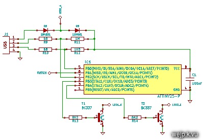
Here is the schematic of my new controller circuit. It consists of the ATtiny25 micro controller, one 100 nF capacitor, two diodes (for lowering the 5 V supply voltage), a few resistors and two BC337 transistors for switching the LEDs. It would probably be a good idea to use an additional capacitor in parallel to the supply voltage with ~ 100 µF or so, when using very long USB cables. As the available space is rather limited, I did not include one, though.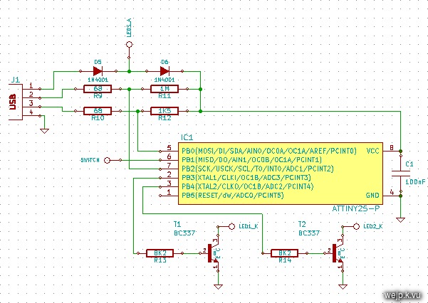
The new controller board connected to the LEDs and the button can be seen in the following picture.
Because of the Mini USB connector's different shape and position, I had to enlarge the hole for the connector. I did not modify the silicone skin in any way, though.
The new PCB needs to be of exactly the same size as the old one to fit into its place. You can see the (partly) reassembled SPÖKA light in the following pictures.
The reassembled inner body...
...and the USB cable attached to the night light still without its skin...
..and then with the skin reattached:
Firmware
Even though I want to use the modded SPÖKA light with a computer, I still wanted to be able to use a simple USB power supply (like one of those USB phone chargers) and still be able to turn it on, which is why I designed the new firmware to allow that.The new firmware can operate in a few different modes. The default mode allows the light to be turned on even without a computer. With the button one can cycle through three colors (blue, green, turquoise). An algorithm for fading through various color combinations did not fit into the 2K of controller memory, so that mode is not available in stand-alone mode. It is available when connected to a computer, though.
When connected to a computer, one can configure the light in different ways. Each color can be turned on individually (with configurable brightness). Also, the button's behavior can be configured. By default, the button works as described above (cycling through those three colors). Another possible configuration for the button is to only turn the light off when it had been turned on previously. The third option for the button is to do nothing to the lights but instead report a button press through USB to the computer. That way the software on the host side can decide how to react to a button press.
When connecting the device to a Linux computer, the kernel log says something like the following about the device:
generic-usb 0003:16C0:05DF.0002: hiddev0,hidraw1: USB HID
v1.01 Device [wejp.k.vu SPOKA] on usb-0000:00:12.0-2/input0
The Makefile for the firmware can build the firmware (make hex) and flash it onto the controller (make program). To build it the avr-gcc is needed, to flash it avrdude is needed. Also, as the call to avrdude for flashing is specific to the programmer used, the AVRDUDE=.. line in the Makefile needs to match the programmer that is being used.
Host computer software
I have written a little utility for controlling the light with a computer. As I am using Linux on my computers, the software has been designed to work in Linux. It should work on other POSIX-compatible operating systems too. To use it with Windows it probably needs to be modified a little. There is a libusb port for Windows, so that part should probably work somehow, but the whole background process thing is most likely done differently on Windows.The software consists of two components. A little daemon that does the actual talking with the SPÖKA light and a command line utility that talks to the daemon. That way, one can tell the daemon to e.g. slowly cycle through different colors and then the daemon does its job in the background until one tells it to do something else. With that software it would also be possible to configure the light such that it flashes when an email or instant message arrives, given that the IM/email program supports calling external programs for such an event.
To be able to talk to the USB device, the user running the daemon needs the permissions to do that. When running it as root, it automatically has all the permissions it needs, so there is nothing to be done in that case. When running it with an ordinary user, the neccessary permissions can be granted through an udev rule. Such rules can be created by adding a file to the /etc/udev/rules.d/ directory. So to allow user access to the SPÖKA USB device, I have added a file called "10-spoka.rules" with the following content:
ACTION!="add|change", GOTO="spoka_rules_end"
SUBSYSTEM=="usb_device", GOTO="spoka_rules_real"
SUBSYSTEM=="usb", GOTO="spoka_rules_real"
SUBSYSTEM!="usb", GOTO="spoka_rules_end"
LABEL="spoka_rules_real"
ATTR{idVendor}=="16c0", ATTR{idProduct}=="05df", MODE="664",
GROUP="users"
LABEL="spoka_rules_end"
This grants read/write access to the device for all users in the "users" group.
After creating that file, udev needs to be restarted to reload the configuration.When the host software has been compiled with the Makefile inside the "tool" directory, there is an executable file called "spokausb". Executing that file with the -d option starts the daemon in the background:
$ ./spokausb -dOnce the daemon is running one can send commands to it by calling the spokausb executable again, but with other parameters. Calling it without any parameters prints a little help.
$ ./spokausb
spokausb 0.1.0
Usage:
  ./spokausb [option] [...]
Options:
 -d  .................................... start daemon
 --led{lednum}={brightness}  ............ set brightness of LED
 --led{lednum}+={brightness increase}  .. increase brightness of LED
 --led{lednum}-={brightness decrease}  .. decrease brightness of LED
 --button=  ........ configure button mode
 --fade   ............................... slowly cycle through all colors
 --flash  ............................... flash repeatedly
 --freeze  .............................. stop cycling through colors
 --read-button  ......................... read button state
 --read-led{lednum}  .................... reade LED state
 --help/-h  ............................. this help
So to turn on the blue LEDs at full brightness one would run:
$ ./spokausb --led1=255Or to turn on all LEDs at medium brightness one could execute the following command:
$ ./spokausb --led1=128 --led2=128This would cause the SPÖKA light to light up in a turquoise color.
To terminate the daemon one can simply kill it.
killall spokausbThis shuts down the daemon cleanly.
Possible modifications
There are a few things that I can think of, which could be done differently.First, the circuit could be modified to support a third color, so the round SPÖKA light could be used as well. This would require to disable the RESET pin on the ATtiny25 to be able to use it as an ordinary I/O pin. Once that has been done, the controller can no longer be reprogrammed using the normal programming mode. So either one needs to program it before setting the fuses, or a programmer supporting high voltage serial programming is needed.
Another possible modification would be to use hardware PWM to control the LEDs, instead of doing that with a software routine. The advantage of this would be that the PWM could be done without the CPU. That would leave the CPU with basically only handling the USB stuff. This would also mean, that USB transfers would not be able to interrupt the PWM routine. Because the hardware PWM can only be used on specific pins one would have to re-route one of the LEDs, which is kind of difficult to do on that small PCB. Also, as there are only two PWM channels available on the ATtiny25 this would not be possible for the three color SPÖKA light.
As already mentioned abobe, another thing that comes to my mind is the addition of a capacitor with about 100 µF in parallel to the power supply line, to stabilize it a bit. When using a very long USB wire (several meters) this might actually be necessary. Due to the very limited amount of available space, I did not include such a capacitor. I had no problems with unstable supply voltage, though.
Of course one could also use a larger micro controller (as in higher memory capacity) like an ATtiny45 or ATtiny85 (which come with twice/four times the the memory) and add more features to the firmware. I simply liked the idea of using one of the smallest AVR controllers. It is also the cheapest of those three.
Last but not least, one could modify the firmware such that it acts like a real HID device and exposes the button of the SPÖKA light as a one key keyboard. This would certainly require a controller with more memory (e.g. ATtiny45).
There are probably a lot more things one could do differently/better. If you have any ideas, suggestions or questions, you are welcome to leave a comment or write me an e-mail.
spokausb-0.1.0.tar.gz (Firmware and host utility (96 kB, GPLv2)
md5sum: bf50712e1b5160dfd82f7ee50e9909aa
Video
Update: Here is a little video showing the USB SPÖKA light in action. Sorry for the poor quality. What I'm doing in the video is basically just sending a few commands from the computer (running a terminal program) to the USB SPÖKA. Unfortunately the camera automatically adjusts its brightness control (which I can't turn off) when the SPÖKA changes its brightness, so one cannot really see the fading effect.The video should play fine in at least the Chrome, Firefox and Opera browsers.